
Introductory Electronics | O Level Physics 5054 & IGCSE Physics 0625 | Detailed Free Notes To Score An A Star (A*)
Topics:
- Thermionic Emission
- Parts of CRO
- Properties of Electrons
- Working of CRO
- Measurement of Voltage and Time Period CRO
- Circuit Components
- Resistor Color Coding
Thermionic Emission:
The process through which electrons are emitted from red-hot filament. Flow of electron require high positive potential or low gas pressure.
Parts of Cathode Ray Oscilloscope (CRO):
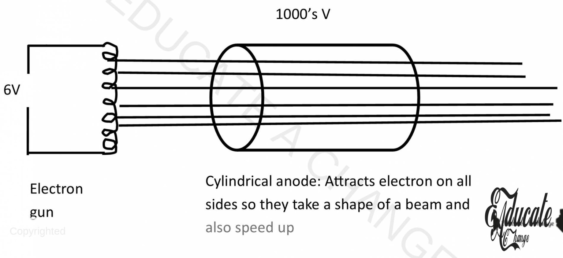
- Electron gun
- Deflecting plates (x and y plates)
- Florescent screen
Properties of Electrons:
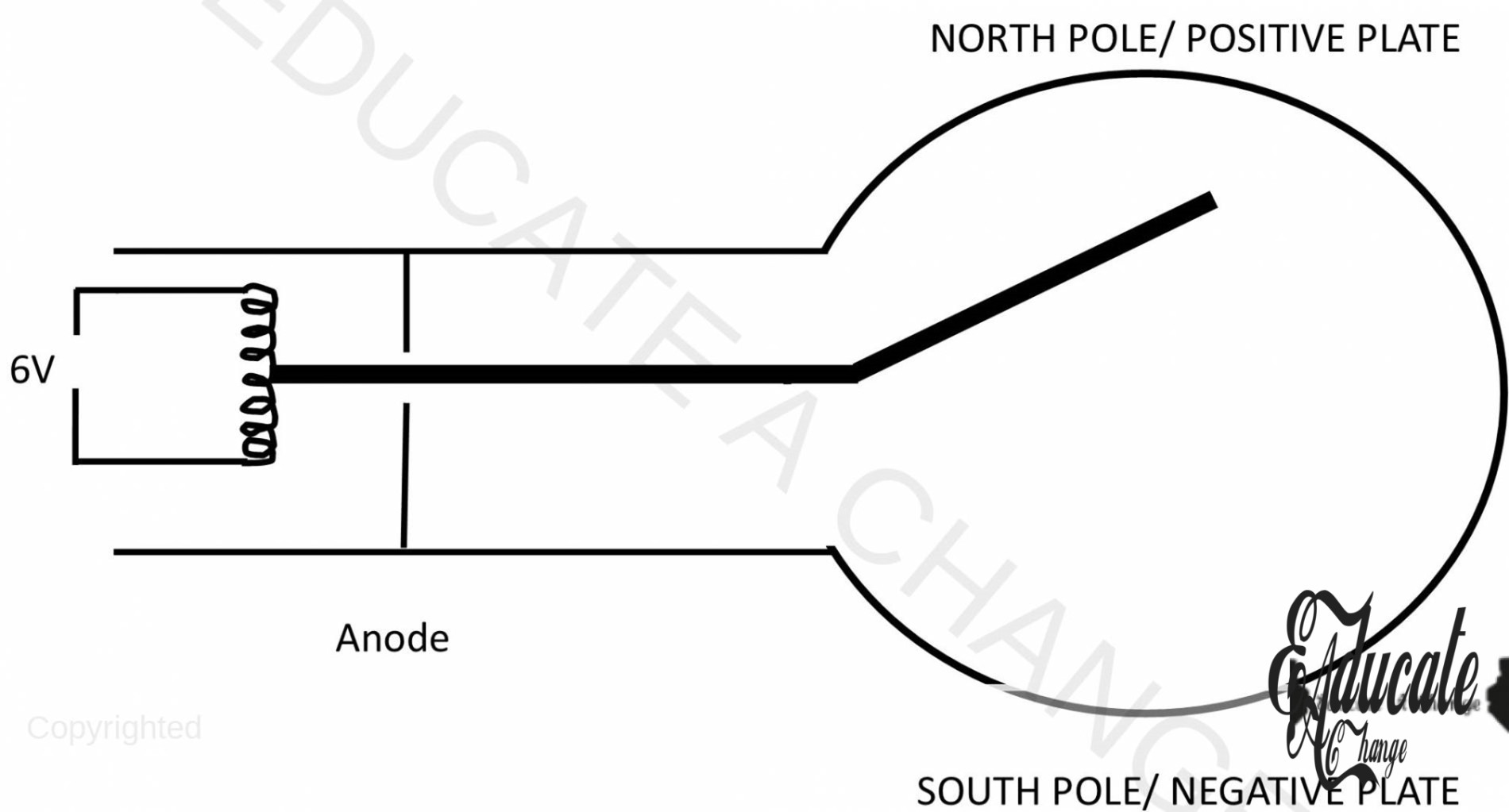
- Flow of electron is against conventional current.
- Electron flow from negative to positive
- Electrons are affected by both electric and magnetic fields. As electrons have negative charge, they bend/ attract towards positive/ north side.
Working of CRO:
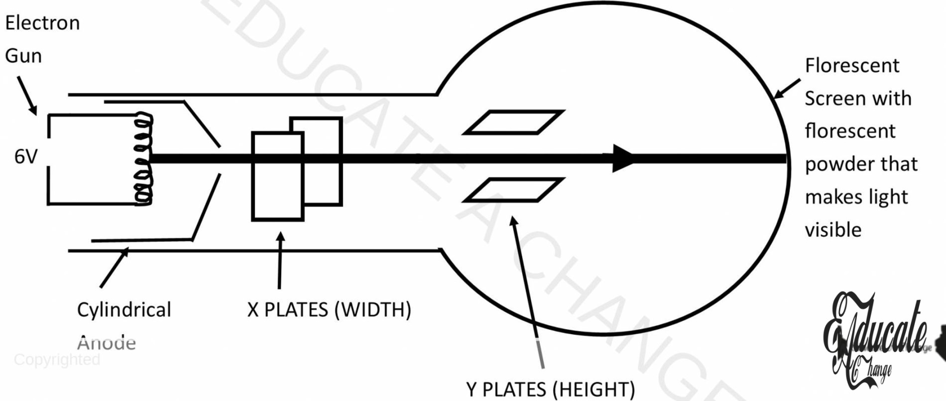
- The electron gun fires the electrons.
- The cylindrical anode attracts the electrons from all sides making them form a beam.
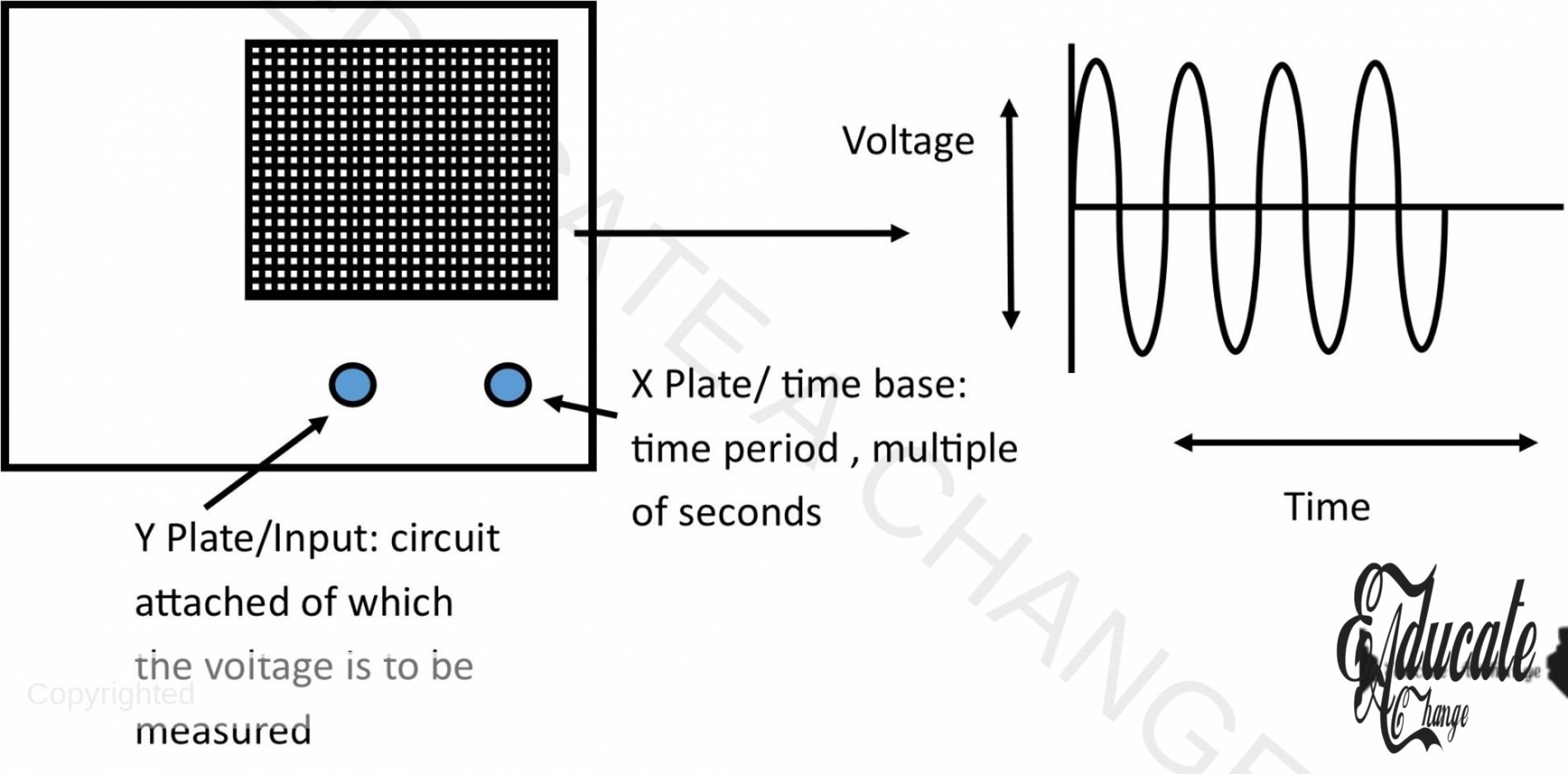
- X plates are used to adjust the width of the beam
- Y plates are used to adjust the height of the beam.
- The beam strikes with the florescent screen and the florescent powder makes the light visible.
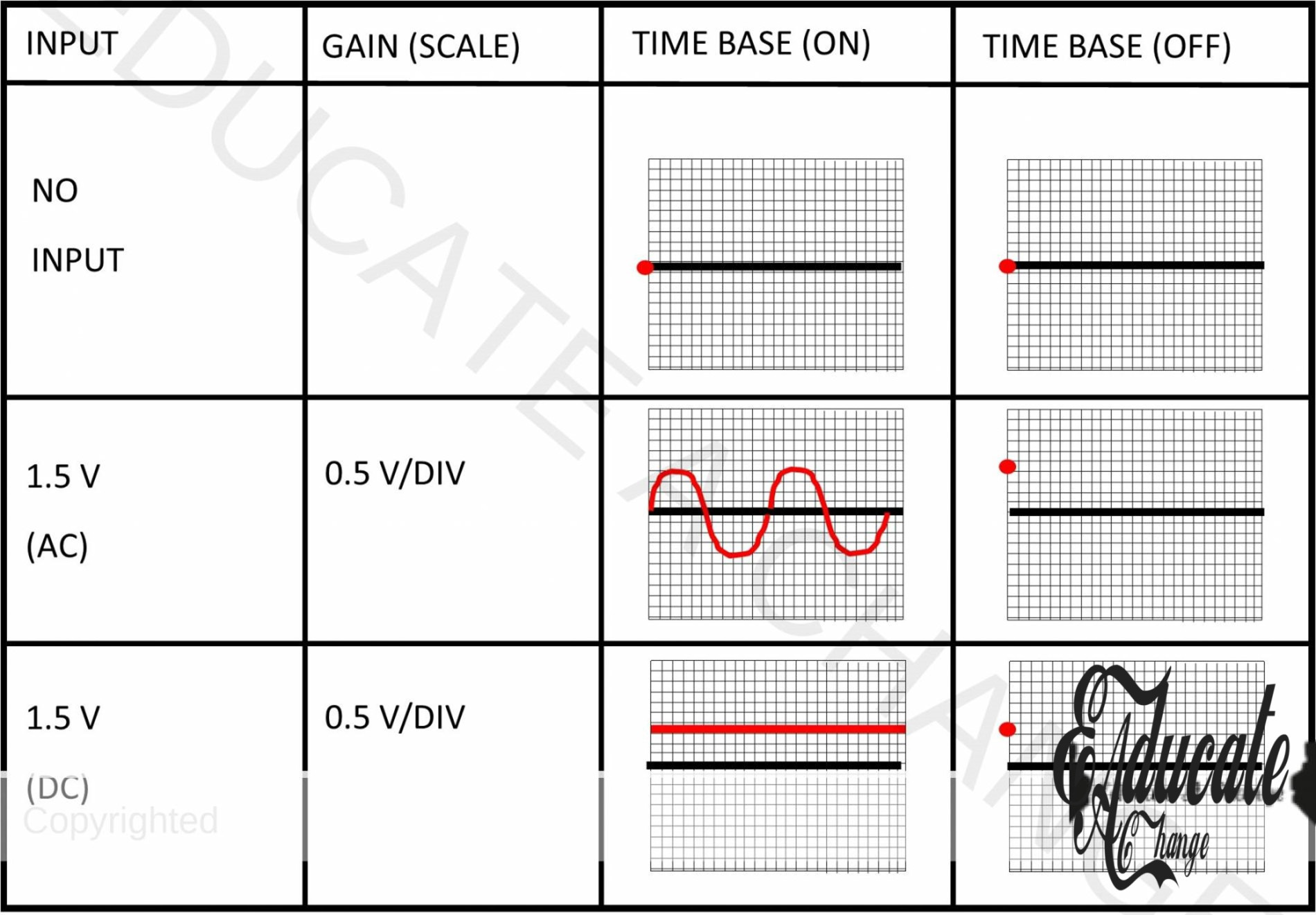
Measurement of Voltage and Time Period CRO:
CRO can be used to show waveforms, measure PD and measure short intervals of time.
Circuit Components:
Resister:
Restricts the flow of current
Thermistor:
Used as a temperature sensor, as temperature increases, its resistance decreases
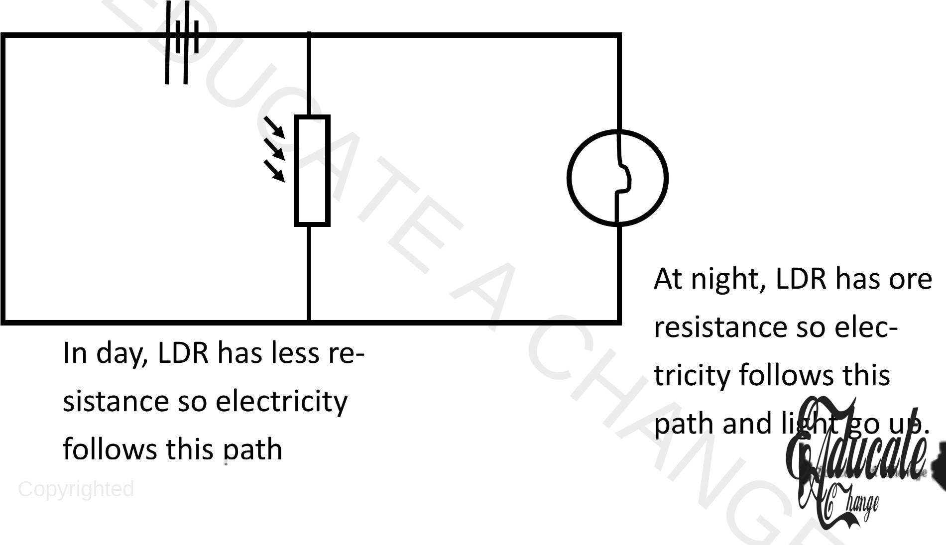
Light-Dependent Resistor (LDR):
By increasing light intensity, its resistance decreases; used as an input sensor
Input Transducers:
These types of devices convert analogue quantity to current signal.
Potential Divider:
Divides potential among components V1 = R1/Rsum x Vtotal
Diode:
Allows current to pass on only one direction
Light emitting Diode:
LEDS emit light and allow current to pass through in only one direction
Capacitor:
Capacitors store charge while current is flowing. When disconnected from the supply, they discharge the stored current.
Resistor Color Coding:
Resistors have colored lines that depict different codes for their resistances. The first two lines indicate the numbers and the third band represents the number of zeros. The codes are as follows:
| Color | Value |
| Black | 0 |
| Brown | 1 |
| Red | 2 |
| Orange | 3 |
| Yellow | 4 |
| Green | 5 |
| Blue | 6 |
| Violet | 7 |
| Grey | 8 |
| White | 9 |
The third band allows the addition of zeros, up to 9 zeros which mean very large and small resistances can be depicted by the color coding.